


Main Menu
Useful Links
Contact us
Follow us
© 2025 Omnitron Systems Technology, Inc. All Rights Reserved. | Privacy Policy
Dual Device Mode Application
This Dual Device feature is extremely useful when two isolated networks domains share a single network distribution location.
The example below depicts a scenario where a surveillance security (purple) network and a Wi-Fi (green) network are sharing a single hub distribution location. Using the two uplinks and the Dual Switch mode facilitates using a single PoE switch driving both the Cameras and the Wi-Fi Access Points while maintaining isolation between the networks.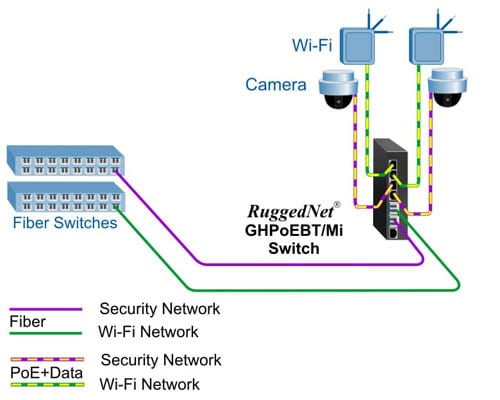
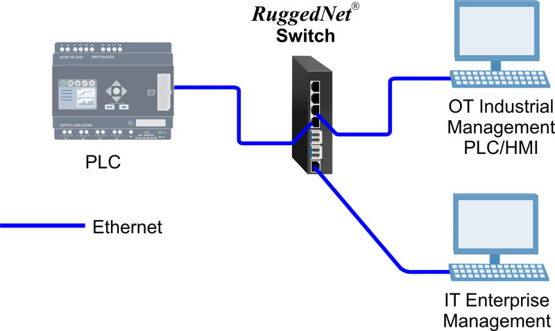
Modbus Application
Modbus is one of the oldest and most popular communication protocols used in industrial automation. Modbus-TCP is the Modbus RTU protocol with a TCP interface running on Ethernet. Omnitron?s Modbus-aware switches seamlessly connect IT (Information Technology Networks) and OT (Operational Technology Networks).
The RuggedNet GHPoEBT/Mi replaces the GHPoE/Mi and is recommended for all new designs.
Additional Features
*100Mbps supported with 100M SGMII SFP Transceivers
| RuggedNet GHPoEBT/Mi IEEE 802.3bt 60W Models | |||||||||||||
|---|---|---|---|---|---|---|---|---|---|---|---|---|---|
| Fiber Type | Distance | Connector Type | Tx/Rx Lambda (nm) | Min. Tx Power (dBm) | Max. Tx Power (dBm) | Min. Rx Power (dBm) | Max. Rx Power (dBm) | Min Atten (dB) | Link Budget (dB) | ||||
| ST | SC | LC | SFP | RJ-45 | |||||||||
| MM/DF | 220/550m1 | 3300B-0-14-pZ | 3302B-0-14-pZ | 3306B-0-14-pZ | - | - | 850/850 | -10 | -4 | -17 | -3 | - | 7 |
| MM/DF (x2) | 220/550m1 | - | - | 3306B-0-24-pZ | - | - | 850/850 | -10 | -4 | -17 | -3 | - | 7 |
| MM/DF | 2km | - | 3302B-6-14-pZ | - | - | - | 1310/1310 | -9.5 | -3 | -19.5 | -3 | - | 10 |
| SM/DF | 12km | 3301B-1-14-pZ | 3303B-1-14-pZ | 3307B-1-14-pZ | - | - | 1310/1310 | -9.5 | -3 | -19.5 | -3 | - | 10 |
| SM/DF (x2) | 12km | - | - | 3307B-1-24-pZ | - | - | 1310/1310 | -9.5 | -3 | -19.5 | -3 | - | 10 |
| SM/DF | 34km | - | 3303B-2-14-pZ | - | - | - | 1310/1310 | -5 | 0 | -23 | -3 | 3 | 18 |
| SM/DF | 80km | - | 3303B-3-14-pZ | - | - | - | 1550/1550 | -5 | 0 | -23 | -3 | 3 | 18 |
| SM/DF | 110km | - | 3303B-4-14-pZ | - | - | - | 1550/1550 | 0 | 5 | -24 | -3 | 8 | 24 |
| SM/DF | 140km | - | 3303B-5-14-pZ | - | - | - | 1550/1550 | 2 | 5 | -28 | -8 | 13 | 30 |
| MM/SF2 | 220/550m1 | - | 3310B-0-14-pZ | - | - | - | 1310/1550 | -9 | -3 | -18 | -3 | - | 9 |
| MM/SF2 | 220/550m1 | - | 3311B-0-14-pZ | - | - | - | 1550/1310 | -9 | -3 | -18 | -3 | - | 9 |
| SM/SF2 | 20km |
- | 3310B-1-14-pZ | - | - | - | 1310/1550 | -9.5 | -3 | -20 | -3 | - | 10.5 |
| SM/SF2 | 20km |
- | 3311B-1-14-pZ | - | - | - | 1550/1310 | -9.5 | -3 | -20 | -3 | - | 10.5 |
| SM/SF2 | 40km |
- | 3310B-2-14-pZ | - | - | - | 1310/1550 | -3 | 0 | -20 | -3 | 3 | 17 |
| SM/SF2 | 40km |
- | 3311B-2-14-pZ | - | - | - | 1550/1310 | -3 | 0 | -20 | -3 | 3 | 17 |
| SFP (x1) | - | - | - | - | 3319B-0-14-pZ | - | - | - | - | - | - | - | - |
| SFP (x2) | - | - | - | - | 3319B-0-24-pZ | - | - | - | - | - | - | - | - |
| RJ-45 (x2) | 100m | - | - | - | - | 3319B-1-24-pZ | - | - | - | - | - | - | - |
|
1 62.5/125?m, 100/140?m multimode fiber up to 220m. 50/125?m multimode fiber up to 550m. 2 When using single-fiber (SF) models, the Tx wavelength on one end has to match the Rx wavelength on the other. MM = Multimode, SM = Single-mode, DF = Dual Fiber, SF = Single-fiber Contact Omnitron for other fiber options. Order the appropriate SFPs separately. Visit the Optical Transceivers web page. |
|||||||||||||
| 1 = Single DC 2-Pin Terminal Power Connector |
| 2 = Dual DC 2-Pin Terminal Power Connectors |
| Z = Extended temperature (-40 to 75?C) |
| RuggedNet GHPoEBT/Mi IEEE 802.3bt 100W Models | |||||||||||||
|---|---|---|---|---|---|---|---|---|---|---|---|---|---|
| Fiber Type | Distance | Connector Type | Tx/Rx Lambda (nm) | Min. Tx Power (dBm) | Max. Tx Power (dBm) | Min. Rx Power (dBm) | Max. Rx Power (dBm) | Min Atten (dB) | Link Budget (dB) | ||||
| ST | SC | LC | SFP | RJ-45 | |||||||||
| MM/DF | 220/550m1 | 3340B-0-14-pZ | 3342B-0-14-pZ | 3346B-0-14-pZ | - | - | 850/850 | -10 | -4 | -17 | -3 | - | 7 |
| MM/DF (x2) | 220/550m1 | - | - | 3346B-0-24-pZ | - | - | 850/850 | -10 | -4 | -17 | -3 | - | 7 |
| MM/DF | 2km | - | 3342B-6-14-pZ | - | - | - | 1310/1310 | -9.5 | -3 | -19.5 | -3 | - | 10 |
| SM/DF | 12km | 3341B-1-14-pZ | 3343B-1-14-pZ | 3347B-1-14-pZ | - | - | 1310/1310 | -9.5 | -3 | -19.5 | -3 | - | 10 |
| SM/DF (x2) | 12km | - | - | 3347B-1-24-pZ | - | - | 1310/1310 | -9.5 | -3 | -19.5 | -3 | - | 10 |
| SM/DF | 34km | - | 3343B-2-14-pZ | - | - | - | 1310/1310 | -5 | 0 | -23 | -3 | 3 | 18 |
| SM/DF | 80km | - | 3343B-3-14-pZ | - | - | - | 1550/1550 | -5 | 0 | -23 | -3 | 3 | 18 |
| SM/DF | 110km | - | 3343B-4-14-pZ | - | - | - | 1550/1550 | 0 | 5 | -24 | -3 | 8 | 24 |
| SM/DF | 140km | - | 3343B-5-14-pZ | - | - | - | 1550/1550 | 2 | 5 | -28 | -8 | 13 | 30 |
| MM/SF2 | 220/550m1 | - | 3350B-0-14-pZ | - | - | - | 1310/1550 | -9 | -3 | -18 | -3 | - | 9 |
| MM/SF2 | 220/550m1 | - | 3351B-0-14-pZ | - | - | - | 1550/1310 | -9 | -3 | -18 | -3 | - | 9 |
| SM/SF2 | 20km |
- | 3351B-1-14-pZ | - | - | - | 1310/1550 | -9.5 | -3 | -20 | -3 | - | 10.5 |
| SM/SF2 | 20km |
- | 3351B-1-14-pZ | - | - | - | 1550/1310 | -9.5 | -3 | -20 | -3 | - | 10.5 |
| SM/SF2 | 40km |
- | 3351B-2-14-pZ | - | - | - | 1310/1550 | -3 | 0 | -20 | -3 | 3 | 17 |
| SM/SF2 | 40km |
- | 3351B-2-14-pZ | - | - | - | 1550/1310 | -3 | 0 | -20 | -3 | 3 | 17 |
| SFP (x1) | - | - | - | - | 3359B-0-14-pZ | - | - | - | - | - | - | - | - |
| SFP (x2) | - | - | - | - | 3359B-0-24-pZ | - | - | - | - | - | - | - | - |
| RJ-45 (x2) | 100m | - | - | - | - | 3359B-1-24-pZ | - | - | - | - | - | - | - |
|
1 62.5/125?m, 100/140?m multimode fiber up to 220m. 50/125?m multimode fiber up to 550m. 2 When using single-fiber (SF) models, the Tx wavelength on one end has to match the Rx wavelength on the other. MM = Multimode, SM = Single-mode, DF = Dual Fiber, SF = Single-fiber Contact Omnitron for other fiber options. Order the appropriate SFPs separately. Visit the Optical Transceivers web page. |
|||||||||||||
| 1 = Single DC 2-Pin Terminal Power Connector |
| 2 = Dual DC 2-Pin Terminal Power Connectors |
| Z = Extended temperature (-40 to 75?C) |
| Model Number | Description | 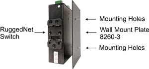 |
|---|---|---|
| 8260-3 | Wall Mounting Plate | |
| 8260-0 | 19" rack mount shelf |
| Model | Product Operating Temperature Range | Watts Required | Industrial Power Supply Model and Operating Temperature Range | |
|---|---|---|---|---|
| -25 to 70C | -30 to 70C | |||
| GHPoEBT/Mi 60W | Commercial / Wide / Extended | 250 watts | 9170-PS-480 | - |
| GHPoEBT/Mi 100W | Commercial / Wide | 410 watts | 9170-PS-480 | - |
| GHPoEBT/Mi 100W | Extended | 410 watts | - | 9170-PS-960 |
RuggedNet GHPoEBT/Mi (Data Sheet)
RuggedNet GHPoEBT/Mi (Quick Start)
RuggedNet Command Line Interface (User Manual)
RuggedNet Web Interface (User Manual)
OmniConverter / RuggedNet 2.5 Hierarchical CLI (User Manual)
Wall Mount Plate (User Manual)
9170-PS-480-Industrial-Power-Supply
9170-PS-960-Industrial-Power-Supply
3300B-0-14-1Z, 3300B-0-14-2Z, 3301B-1-14-1Z, 3301B-1-14-2Z, 3302B-0-14-1Z, 3302B-0-14-2Z, 3302B-6-14-1Z, 3302B-6-14-2Z, 3303B-1-14-1Z, 3303B-1-14-2Z, 3303B-2-14-1Z, 3303B-2-14-2Z, 3303B-3-14-1Z, 3303B-3-14-2Z, 3303B-4-14-1Z, 3303B-4-14-2Z, 3303B-514-1Z, 3303B-514-2Z, 3306B-0-14-1Z, 3306B-0-14-2Z, 3306B-0-24-1Z, 3306B-0-24-2Z, 3307B-1-14-1Z, 3307B-1-14-2Z, 3307B-1-24-1Z, 3307B-1-24-2Z, 3310B-0-14-1Z, 3310B-0-14-2Z, 3311B-0-14-1Z, 3311B-0-14-2Z, 3310B-1-14-1Z, 3310B-1-14-2Z, 3311B-1-14-1Z, 3311B-1-14-2Z, 3310B-2-14-1Z, 3310B-2-14-2Z, 3311B-2-14-1Z, 3311B-2-14-2Z, 3319B-0-14-1Z, 3319B-0-14-2Z, 3319B-0-24-1Z, 3319B-1-24-1Z, 3319B-0-24-2Z, 3319B-1-24-2Z, 3340B-0-14-1Z, 3340B-0-14-2Z, 3341B-1-14-1Z, 3341B-1-14-2Z, 3342B-0-14-1Z, 3342B-0-14-2Z, 3342B-6-14-1Z, 3342B-6-14-2Z, 3343B-1-14-1Z, 3343B-1-14-2Z, 3343B-2-14-1Z, 3343B-2-14-2Z, 3343B-3-14-1Z, 3343B-3-14-2Z, 3343B-4-14-1Z, 3343B-4-14-2Z, 3343B-5-14-1Z, 3343B-5-14-2Z, 3346B-0-14-1Z, 3346B-0-14-2Z, 3346B-0-24-1Z, 3346B-0-24-2Z, 3347B-1-14-1Z, 3347B-1-14-2Z, 3347B-1-24-1Z, 3347B-1-24-2Z, 3350B-0-14-1Z, 3350B-0-14-2Z, 3351B-0-14-1Z, 3351B-0-14-2Z, 3350B-1-14-1Z, 3350B-1-14-2Z, 3351B-1-14-1Z, 3351B-1-14-2Z, 3350B-2-14-1Z, 3350B-2-14-2Z, 3351B-2-14-1Z, 3351B-2-14-2Z, 3359B-0-14-1Z, 3359B-0-14-2Z, 3359B-0-24-1Z, 3359B-1-24-1Z, 3359B-0-24-2Z, 3359B-1-24-2Z,
The RuggedNet GHPoEBT/Mi is a managed Industrial Ethernet switch that features two 1/10G uplink ports and four 10/100/1000 RJ-45 IEEE 802.3bt 60W or 100W PoE user ports.
All models support Directed Switch mode, which directs multicast traffic, such as video, to the appropriate uplink port, preventing multicast traffic from flooding other network ports.
Models with two fiber or two copper uplink ports support redundant uplinks, industrial ring Media Redundancy Protocol (MRP), Rapid Spanning Tree Protocol (RSTP) and daisy-chain configurations for high availability industrial network applications.
Models with two fiber or two copper uplink ports also support Dual Device mode that enables the switches to operate as two independent and isolated Ethernet switches.
The mode of operation can be configured using easily accessible DIP-switches or using Web, Telnet, SSH, SNMPv1/v2c/v3 or Serial Console management interfaces. IPv4 and IPv6 are supported on the switches. These management interfaces provide access to filtering and security options, such as, broadcast storm prevention, IGMP, IEEE 802.1x, RADIUS, TACACS+ and Access Control Lists. Email notification and alarm reporting is provided.
The RuggedNet PoE switches are available with fixed fiber ST, SC, and LC connectors or Small Form Pluggable (SFP) transceiver ports. Fiber ports support multimode or single-mode and dual fiber or single-fiber with distances up to 140km. SFP models support a variety of distances in standard, CWDM and DWDM wavelengths.
The switches feature a PoE Power Reset function that enables the user to remotely power-cycle and reset each PD, such as a camera or access point. They also feature a configurable Heartbeat Reset function that automatically pings the attached PDs and automatically power cycles and resets the PDs when detecting a heartbeat loss. The Power Reset and the Heartbeat Reset functions save time and expense by eliminating the need to dispatch manpower to remote network sites.
An alarm relay is available to detect user configured events. The relay contact can be configured for normally open or normally closed operation. One alarm input is available for detecting external events such as door open or closed.
Power / Voltage Requirements and Specifications per IEEE
|
||||||||||||||||||||||||||||||||||||||||||||||||||||||||||||||||||||||||||||||||||||||||||||||||||||||||||||||||
Main Menu
Useful Links
Contact us
Follow us
© 2025 Omnitron Systems Technology, Inc. All Rights Reserved. | Privacy Policy
