


Main Menu
Useful Links
Contact us
Follow us
© 2025 Omnitron Systems Technology, Inc. All Rights Reserved. | Privacy Policy
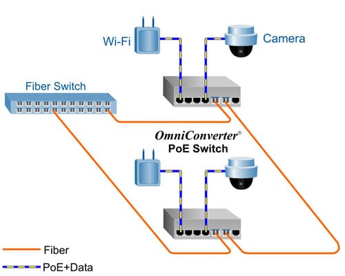
Daisy-Chain and Ring Topology Network Application
This example demonstrates the daisy chaining and ring capabilities of the OmniConverter. In this application each OmniConverter switch connects to its neighboring switches via its uplink ports eventually closing the ring.
Using this network architecture combined with ring protection protocols such as Media Redundancy Protocol (MRP) or Rapid Spanning Tree Protocol (RSTP) facilitates a highly resilient network required in mission critical applications.
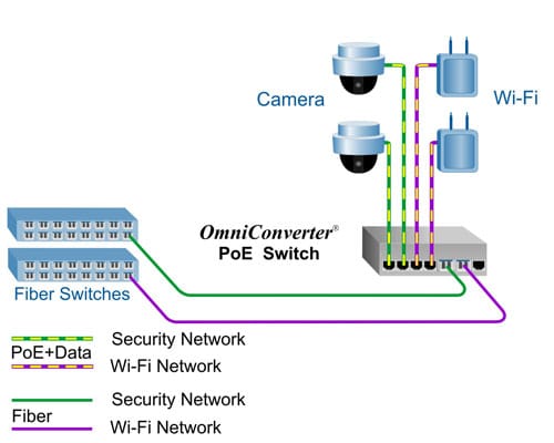
Dual Device Mode Application
This Dual Device feature is extremely useful when two isolated networks domains share a single network distribution location.
The example below depicts a scenario where a surveillance security (green) network and a Wi-Fi (purple) network are sharing a single hub distribution location. Using the two uplinks and the Dual Switch mode facilitates using a single PoE switch driving both the Cameras and the Wi-Fi Access Points while maintaining isolation between the networks.
PoE Power Multi-Day Scheduler
The web management allows you to automatically power on/off connected PD devices at pre-defined times of the day, which conserves energy and increases network security. For example, network managers can schedule to turn off power to their VoIP phones or WiFi Devices after business hours preventing unauthorized access and conserving energy, while having continuous PoE power to their Security Surveillance cameras 24 hours a day.

The OmniConverter GHPoEBT/M replaces the GHPoE/M and is recommended for all new designs.
ADDITIONAL FEATURES
*100Mbps supported with 100M SGMII SFP Transceivers
| OmniConverter GHPoEBT/M IEEE 802.3bt 60W Models | |||||||||||||
|---|---|---|---|---|---|---|---|---|---|---|---|---|---|
| Fiber Type | Distance | Connector Type | Tx/Rx Lambda (nm) | Min. Tx Power (dBm) | Max. Tx Power (dBm) | Min. Rx Power (dBm) | Max. Rx Power (dBm) | Min Atten (dB) | Link Budget (dB) | ||||
| ST | SC | LC | SFP | RJ-45 | |||||||||
| MM/DF | 220/550m1 | 3100B-0-14-pt | 3102B-0-14-pt | 3106B-0-14-pt | - | - | 850/850 | -10 | -4 | -17 | -3 | - | 7 |
| MM/DF (x2) | 220/550m1 | - | - | 3106B-0-24-pt | - | - | 850/850 | -10 | -4 | -17 | -3 | - | 7 |
| MM/DF | 2km | - | 3102B-6-14-pt | - | - | - | 1310/1310 | -9.5 | -3 | -19.5 | -3 | - | 10 |
| SM/DF | 12km | 3101B-1-14-pt | 3103B-1-14-pt | 3107B-1-14-pt | - | - | 1310/1310 | -9.5 | -3 | -19.5 | -3 | - | 10 |
| SM/DF (x2) | 12km | - | - | 3107B-1-24-pt | - | - | 1310/1310 | -9.5 | -3 | -19.5 | -3 | - | 10 |
| SM/DF | 34km | - | 3103B-2-14-pt | - | - | - | 1310/1310 | -5 | 0 | -23 | -3 | 3 | 18 |
| SM/DF | 80km | - | 3103B-3-14-pt | - | - | - | 1550/1550 | -5 | 0 | -23 | -3 | 3 | 18 |
| SM/DF | 110km | - | 3103B-4-14-pt | - | - | - | 1550/1550 | 0 | 5 | -24 | -3 | 8 | 24 |
| SM/DF | 140km | - | 3103B-5-14-pt | - | - | - | 1550/1550 | 2 | 5 | -28 | -8 | 13 | 30 |
| MM/SF2 | 220/550m1 | - | 3110B-0-14-pt | - | - | - | 1310/1550 | -9 | -3 | -18 | -3 | - | 9 |
| MM/SF2 | 220/550m1 | - | 3111B-0-14-pt | - | - | - | 1550/1310 | -9 | -3 | -18 | -3 | - | 9 |
| SM/SF2 | 20km |
- | 3110B-1-14-pt | - | - | - | 1310/1550 | -9.5 | -3 | -20 | -3 | - | 10.5 |
| SM/SF2 | 20km |
- | 3111B-1-14-pt | - | - | - | 1550/1310 | -9.5 | -3 | -20 | -3 | - | 10.5 |
| SM/SF2 | 40km |
- | 3110B-2-14-pt | - | - | - | 1310/1550 | -3 | 0 | -20 | -3 | 3 | 17 |
| SM/SF2 | 40km |
- | 3111B-2-14-pt | - | - | - | 1550/1310 | -3 | 0 | -20 | -3 | 3 | 17 |
| SFP (x1) | - | - | - | - | 3119B-0-14-pt | - | - | - | - | - | - | - | - |
| SFP (x2) | - | - | - | - | 3119B-0-24-pt | - | - | - | - | - | - | - | - |
| RJ-45 (x2) | 100m | - | - | - | - | 3119B-1-24-pt | - | - | - | - | - | - | - |
|
1 62.5/125?m, 100/140?m multimode fiber up to 220m. 50/125?m multimode fiber up to 550m. 2 When using single-fiber (SF) models, the Tx wavelength on one end has to match the Rx wavelength on the other. MM = Multimode, SM = Single-mode, DF = Dual Fiber, SF = Single-fiber Contact Omnitron for other fiber options. Order the appropriate SFPs separately. Visit the Optical Transceivers web page. |
|||||||||||||
| 1 = External AC/DC Adapter, 100 - 240 VAC included, with US Power Cord - See AC/DC Adapter Temperature table |
| 2 = External AC/DC Adapter, 100 - 240 VAC included, No Power Cord - See AC/DC Adapter Temperature table |
| 8 = External AC/DC Adapter, 100 - 240 VAC included, with Japanese Power Cord - See AC/DC Adapter Temperature table |
| 9 = Direct DC 2 pin terminal connector, no AC/DC power adapter |
| <leave blank> = Commercial temperature (0 to 50?C) |
| W = Wide temperature (-40 to 60?C) |
| Z = Extended temperature (-40 to 75?C) - not available for models with AC/DC Power Adapters |
| AC/DC Adapter Temperature Derating - Total Available Wattage to RJ-45 Ports | ||||
|---|---|---|---|---|
| Model | Watts Required | 40?C | 50?C | 60?C |
| GHPoEBT/M 60W | 240 watts | Full Power | 175 watts | 115 watts |
| The AC/DC Adapter Temperature derating table is not applicable to models with DC Terminal (see Ordering table for Direct DC -9 option). The DC Terminal models will provide full PoE power over the operating temperature range of the module as long as the DC input voltage meets the requirements stated in the specification table. | ||||
| OmniConverter GHPoEBT/M IEEE 802.3bt 100W Models | |||||||||||||
|---|---|---|---|---|---|---|---|---|---|---|---|---|---|
| Fiber Type | Distance | Connector Type | Tx/Rx Lambda (nm) | Min. Tx Power (dBm) | Max. Tx Power (dBm) | Min. Rx Power (dBm) | Max. Rx Power (dBm) | Min Atten (dB) | Link Budget (dB) | ||||
| ST | SC | LC | SFP | RJ-45 | |||||||||
| MM/DF | 220/550m1 | 3140B-0-14-pt | 3142B-0-14-pt | 3146B-0-14-pt | - | - | 850/850 | -10 | -4 | -17 | -3 | - | 7 |
| MM/DF (x2) | 220/550m1 | - | - | 3146B-0-24-pt | - | - | 850/850 | -10 | -4 | -17 | -3 | - | 7 |
| MM/DF | 2km | - | 3142B-6-14-pt | - | - | - | 1310/1310 | -9.5 | -3 | -19.5 | -3 | - | 10 |
| SM/DF | 12km | 3141B-1-14-pt | 3143B-1-14-pt | 3147B-1-14-pt | - | - | 1310/1310 | -9.5 | -3 | -19.5 | -3 | - | 10 |
| SM/DF (x2) | 12km | - | - | 3147B-1-24-pt | - | - | 1310/1310 | -9.5 | -3 | -19.5 | -3 | - | 10 |
| SM/DF | 34km | - | 3143B-2-14-pt | - | - | - | 1310/1310 | -5 | 0 | -23 | -3 | 3 | 18 |
| SM/DF | 80km | - | 3143B-3-14-pt | - | - | - | 1550/1550 | -5 | 0 | -23 | -3 | 3 | 18 |
| SM/DF | 110km | - | 3143B-4-14-pt | - | - | - | 1550/1550 | 0 | 5 | -24 | -3 | 8 | 24 |
| SM/DF | 140km | - | 3143B-5-14-pt | - | - | - | 1550/1550 | 2 | 5 | -28 | -8 | 13 | 30 |
| MM/SF2 | 220/550m1 | - | 3150B-0-14-pt | - | - | - | 1310/1550 | -9 | -3 | -18 | -3 | - | 9 |
| MM/SF2 | 220/550m1 | - | 3151B-0-14-pt | - | - | - | 1550/1310 | -9 | -3 | -18 | -3 | - | 9 |
| SM/SF2 | 20km |
- | 3151B-1-14-pt | - | - | - | 1310/1550 | -9.5 | -3 | -20 | -3 | - | 10.5 |
| SM/SF2 | 20km |
- | 3151B-1-14-pt | - | - | - | 1550/1310 | -9.5 | -3 | -20 | -3 | - | 10.5 |
| SM/SF2 | 40km |
- | 3151B-2-14-pt | - | - | - | 1310/1550 | -3 | 0 | -20 | -3 | 3 | 17 |
| SM/SF2 | 40km |
- | 3151B-2-14-pt | - | - | - | 1550/1310 | -3 | 0 | -20 | -3 | 3 | 17 |
| SFP (x1) | - | - | - | - | 3159B-0-14-pt | - | - | - | - | - | - | - | - |
| SFP (x2) | - | - | - | - | 3159B-0-24-pt | - | - | - | - | - | - | - | - |
| RJ-45 (x2) | 100m | - | - | - | - | 3159B-1-24-pt | - | - | - | - | - | - | - |
|
1 62.5/125?m, 100/140?m multimode fiber up to 220m. 50/125?m multimode fiber up to 550m. 2 When using single-fiber (SF) models, the Tx wavelength on one end has to match the Rx wavelength on the other. MM = Multimode, SM = Single-mode, DF = Dual Fiber, SF = Single-fiber Contact Omnitron for other fiber options. Order the appropriate SFPs separately. Visit the Optical Transceivers web page. |
|||||||||||||
| 1 = External AC/DC Adapter, 100 - 240 VAC included, with US Power Cord - See AC/DC Adapter Temperature table |
| 2 = External AC/DC Adapter, 100 - 240 VAC included, No Power Cord - See AC/DC Adapter Temperature table |
| 8 = External AC/DC Adapter, 100 - 240 VAC included, with Japanese Power Cord - See AC/DC Adapter Temperature table |
| 9 = Direct DC 2 pin terminal connector, no AC/DC power adapter |
| <leave blank> = Commercial temperature (0 to 50?C) |
| W = Wide temperature (-40 to 60?C) |
| Z = Extended temperature (-40 to 75?C) - not available for models with AC/DC Power Adapters |
| AC/DC Adapter Temperature Derating - Total Available Wattage to RJ-45 Ports | ||||
|---|---|---|---|---|
| Model | Watts Required | 40?C | 50?C | 60?C |
| GHPoEBT/M 100W | 400 watts | 240 watts | 175 watts | 115 watts |
| The AC/DC Adapter Temperature derating table is not applicable to models with DC Terminal (see Ordering table for Direct DC -9 option). The DC Terminal models will provide full PoE power over the operating temperature range of the module as long as the DC input voltage meets the requirements stated in the specification table. | ||||
| Model Number | Description |
|---|---|
| 8251-0 | DIN-Rail Mounting Clip |
| 8260-0 | 19" rack mount shelf |
| Model | Product Operating Temperature Range | Watts Required | Industrial Power Supply Model and Operating Temperature Range | |
|---|---|---|---|---|
| -25 to 70C | -30 to 70C | |||
| GHPoEBT/M 60W | Commercial / Wide / Extended | 250 watts | 9170-PS-480 | - |
| GHPoEBT/M 100W | Commercial / Wide | 410 watts | 9170-PS-480 | - |
| GHPoEBT/M 100W | Extended | 410 watts | - | 9170-PS-960 |
OmniConverter GHPoEBT/M (Data Sheet)
OmniConverter GHPoEBT/M (Quick Start)
OmniConverter Command Line Interface (User Manual)
OmniConverter Web Interface (User Manual)
OmniConverter / RuggedNet 2.5 Hierarchical CLI (User Manual)
The OmniConverter GHPoEBT/M are compact managed Ethernet switch that features two 1/10G uplink ports and four 10/100/1000 RJ-45 IEEE 802.3bt 60W or 100W PoE user ports.
The OmniConverter PoE switches are standard Layer 2 Ethernet switches that forward frames to any port based on their MAC address.
All models support Directed Switch mode, which directs multicast traffic (such as video) only to the appropriate uplink port, preventing multicast traffic from flooding other network ports. Models with two fiber or two copper uplink ports support redundant uplinks, industrial ring Media Redundancy Protocol (MRP), Rapid Spanning Tree Protocol (RSTP) and daisy-chain configurations for high availability industrial network applications.
Models with two fiber or two copper uplink ports also support Dual Device mode that enables the switches to operate as two independent and isolated Ethernet switches.
The mode of operation can be configured using easily accessible DIP-switches or using Web, Telnet, SSH, SNMPv1/v2c/v3 or Serial Console management interfaces. IPv4 and IPv6 are supported on the switches. These management interfaces provide access to filtering and security options, such as, broadcast storm prevention, IGMP, IEEE 802.1x, RADIUS, TACACS+ and Access Control Lists. Email notification and alarm reporting is provided.
The OmniConverter PoE switches are available with fixed fiber ST, SC, and LC connectors or Small Form Pluggable (SFP) transceiver receptacles. Fiber ports support multimode or single-mode and dual fiber or single-fiber with distances up to 140km. SFP models support a variety of distances in standard, CWDM and DWDM wavelengths.
The switches feature a PoE Power Reset function that enables the user to remotely power-cycle and reset each PD, such as a camera or access point. They also feature a configurable Heartbeat Reset function that automatically pings the attached PDs and automatically power cycles and resets the PDs when detecting a heartbeat loss. The Power Reset and the Heartbeat Reset functions save time and expense by eliminating the need to dispatch manpower to remote network sites.
Power / Voltage Requirements and Specifications per IEEE
|
||||||||||||||||||||||||||||||||||||||||||||||||||||||||||||||||||||||||||||||||||||||||||||||||||||||||||||
Main Menu
Useful Links
Contact us
Follow us
© 2025 Omnitron Systems Technology, Inc. All Rights Reserved. | Privacy Policy
